[Unity Shader Graph Usage and Special Effects Implementation] Column – Direct
The Polygon node is a powerful geometric shape generation tool in Unity URP Shader Graph, specifically used to create regular polygon patterns in shaders. This node provides shader artists and developers with a procedural way to generate a variety of polygonal shapes, from simple triangles to complex circular approximations, all easily achieved by adjusting parameters. In game development, geometric patterns are often used to create sci-fi style interface elements, decorative textures, special effects masks, and various stylized visual effects.
Using Polygon nodes to generate geometry has several significant advantages over traditional texture mapping methods. First, it is fully procedural, meaning all properties of a polygon can be adjusted in real time without the need to re-import textures. Secondly, the generated shapes have infinite resolution and do not suffer from pixelation issues. In addition, procedural generation reduces dependence on external texture files, helping to reduce project size and simplify resource management processes.
The Polygon node works based on mathematical calculations, using the polar coordinate system and trigonometric functions to determine whether a pixel is inside a polygon. This method is not only efficient, but also produces very clear and sharp edges, which is particularly suitable for visual effects that require precise geometric shapes. Understanding the inner workings of this node is crucial to realizing its full potential, and we’ll delve into various aspects of it below.
describe
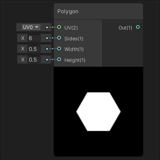
The core function of the Polygon node is to generate regular polygon shapes based on input UV coordinates. Regular polygons refer to polygons in which all sides are of equal length and all interior angles are equal, such as equilateral triangles, squares, regular pentagons, etc. The node determines whether each UV coordinate point is located inside the specified polygon through mathematical calculations, and outputs the corresponding value – usually the inner area of the polygon outputs 1, the outer area outputs 0, and the edge area outputs an intermediate value according to anti-aliasing needs.
The size of the shape generated by this node is controlled by two independent parameters: Width and Height. This separated control allows the user to create non-square polygons, such as elongated hexagons or squashed octagons. By default, when the width and height values are the same, a regular polygon is produced; when the two values are different, the polygon is stretched accordingly along one axis.
One of the most important characteristics of a polygon is its number of sides, which is controlled by the Sides parameter. The number of sides must be an integer value greater than or equal to 3. In theory, a very large value can be set to approximate a circle. In practical applications, the choice of the number of edges depends on specific needs:
A key feature of the Polygon node is that it retains the ability to operate on UV space. This means that the user can offset or tile the resulting shape by connecting the Tiling And Offset nodes. However, it is important to note that the nodes themselves do not automatically repeat the shape – if you tile the UVs directly, the entire polygon pattern will be stretched across the entire UV space, rather than multiple polygons being repeated. To achieve a repeating polygon pattern, you need to first process the UV input through the Fraction node. This technical point is crucial for creating checkerboard or grid-like polygon patterns.
From a technical implementation perspective, the Polygon node can only be used in the fragment shader stage because it requires calculations for each pixel to determine whether it is inside a polygon. This pixel-by-pixel calculation ensures the accuracy of generated shapes and high-quality anti-aliasing effects, but it also means that it is not suitable for use in vertex shaders, because the calculation granularity of vertex shaders does not provide enough precision to define clear geometric edges.
port
The functionality of a Polygon node is implemented through its input and output ports, each of which has a specific role and data type. Understanding the role of these ports is critical to using nodes correctly.
input port
The UV input port is the most basic input of the Polygon node. It receives UV coordinate data of Vector 2 type. This port is typically connected to a UV node in the Shader Graph, but can also be connected to any node that generates Vector 2 data, such as the output of a Tiling And Offset node or the result of other mathematical calculations. The flexibility of the UV input port allows polygons to be placed anywhere in texture space and various transformations to be applied. When not explicitly connected, nodes default to the mesh's base UV coordinates.
The Sides input port controls the number of sides of the generated polygon and accepts values of type Float. Although mathematically the number of edges should be an integer, the port accepts floating point numbers to facilitate dynamically changing edge numbers. In actual calculations, nodes use integer values for the number of edges. The valid range of the number of edges is greater than or equal to 3. When setting a value less than 3, the node may produce undefined behavior or incorrect results. By controlling the Sides value through animation or parameters, you can create interesting effects of polygonal shape deformation, such as gradually changing from a triangle to a circle.
The Width and Height input ports control the size of the polygon in the U and V directions respectively. Both ports accept values of type Float representing the radius or half-width of the polygon in the corresponding direction. When the Width and Height values are equal, a regular polygon is generated; when they are different, the polygon will be stretched in the corresponding direction. This ability to independently control width and height allows users to create polygons of various proportions, not just regular polygons. At a value of 1, the polygon will generally occupy the entire UV space (range from 0 to 1), but this depends on the number of sides and shape of the polygon.
Output port
The Out output port is the main output of the Polygon node and provides a result value of type Float. This value represents the position of the specified position relative to the polygon:
The output values can be used for a variety of purposes, such as directly as transparency values to create shape masks, as blending factors to blend with other textures or colors, or as input to other mathematical calculations. Since the output is a single-channel floating point value, it can be easily integrated into various shader calculations, whether for color, transparency, specularity, or other surface properties.
Port connection practice
In actual use, these ports can be connected in a variety of ways to create complex effects. For example:
Understanding the role and potential connections of each port is key to mastering the use of Polygon nodes. Through creative connections and parameter control, the application range of this node can be greatly expanded.
Generated code example
The functions of the Polygon node are implemented through the underlying HLSL code. Understanding this generated code will help you gain an in-depth understanding of the working principle and potential optimization directions of the node. The following is the possible code implementation of node and its detailed analysis:
void Unity_Polygon_float(float2 UV, float Sides, float Width, float Height, out float Out)
{
    // 定义π常量,用于三角函数计算
    float pi = 3.14159265359;
    // 计算调整后的宽度和高度,考虑多边形边数对表观尺寸的影响
    float aWidth = Width * cos(pi / Sides);
    float aHeight = Height * cos(pi / Sides);
    // 转换UV坐标:从[0,1]范围转到[-1,1]范围,并应用调整后的尺寸
    float2 uv = (UV * 2 - 1) / float2(aWidth, aHeight);
    // 翻转Y轴以匹配常规的坐标系统
    uv.y *= -1;
    // 计算当前UV坐标的极角(从正Y轴顺时针测量)
    float pCoord = atan2(uv.x, uv.y);
    // 计算每条边对应的角度增量
    float r = 2 * pi / Sides;
    // 计算当前角度所属的边,并计算到该边的距离
    float distance = cos(floor(0.5 + pCoord / r) * r - pCoord) * length(uv);
    // 应用抗锯齿并限制输出范围在[0,1]
    Out = saturate((1 - distance) / fwidth(distance));
}
Code analysis
This code can be broken down into several key steps, each corresponding to a specific aspect of polygon generation:
Constant definition and size adjustment: The code first defines the π constant, and then calculates the adjusted width and height (aWidth and aHeight). This adjustment is achieved by multiplying the original size by cos(π/Sides) in order to compensate for the effect of the number of polygon sides on the apparent size. This adjustment is more noticeable for polygons with fewer sides, ensuring that polygons with different sides have a more consistent apparent size under the same size parameters.
Coordinate space conversion: The next step is to convert the input UV coordinates from the standard range to the range, which moves the coordinate origin to the center, which is more in line with the needs of polar coordinate calculations. The coordinates are then divided by the adjusted size to achieve the scaling effect. The Y-axis is flipped to match common coordinate system conventions, where the positive Y-axis is usually upward.
Polar coordinate calculation: Use the atan2 function to calculate the polar angle pCoord of each point. This angle represents the angle between the vectors clockwise from the positive Y axis to the point. The atan2 function can correctly handle all four quadrants compared to the simple atan function, ensuring the accuracy of angle calculations.
Distance calculation: This is the core part of the algorithm. First calculate the angle increment r corresponding to each side, then determine which side the current angle belongs to through floor(0.5 + pCoord / r), then calculate the difference between the current angle and the center angle of the side it belongs to, and finally use the cos function and length to calculate the final distance value. This distance value represents the vertical distance from the current point to the corresponding edge.
Anti-aliasing and output limitation: The last step uses the fwidth function to calculate the rate of change of the distance field to achieve edge anti-aliasing. The saturate function ensures that the output value is limited to the range and avoids invalid values.
Algorithm characteristics
This distance field-based polygon generation method has several important features:
Performance considerations
From a performance perspective, the code uses several transcendental functions (cos, atan2) that are relatively expensive to compute in the shader. In performance-sensitive scenarios, you should consider limiting the number of Polygon nodes used or finding optimization solutions. On modern GPUs, though, the performance impact is generally acceptable for moderate amounts of use.
Understanding this generated code not only helps you use Polygon nodes more efficiently, but also provides the basis for custom modifications and optimizations. For example, users can create variations based on this template to achieve rounded polygons, gradient fills, or other advanced effects.
Practical application examples
Polygon nodes have a wide range of application scenarios in Shader Graph, and they can play an important role from simple shape generation to complex visual effects. The following are some typical application examples and implementation methods.
Basic shape creation
The most basic application is to create various regular polygonal shapes. By adjusting the Sides parameter, different geometries can be easily generated:
In practice, creating a base shape usually only requires connecting a UV node to the UV input of a Polygon node, and then setting the required Sides, Width, and Height parameters. The output can be connected directly to the alpha channel of the main texture to create a shape mask, or multiplied with a color node to assign a color to the shape.
Dynamic polygon effects
By connecting dynamic values to the input ports of a Polygon node, you can create a variety of animations and interactive effects:
These dynamic effects greatly enhance the vitality and appeal of visual expressions, making polygons no longer static decorative elements but active components capable of conveying information and status.
Complex pattern combinations
A single Polygon node is already powerful, but by combining multiple nodes you can create more complex and interesting patterns:
These advanced techniques extend the scope of Polygon nodes, making them a powerful tool for creating complex visual effects. By experimenting with different combinations and parameters, shader artists can develop unique and eye-catching visual styles.
Best practices and tips
To realize the full potential of Polygon nodes and avoid common problems, here are some practical tips and best practices:
Performance optimization
Although Polygon nodes are very useful, improper use can cause performance issues:
quality improvement
Ways to improve the visual effect of polygons:
troubleshooting
Frequently asked questions and solutions:
[Unity Shader Graph Usage and Special Effects Implementation] Column – Direct